The XX Challenge
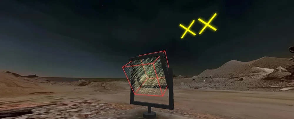
Greetings space explorers! It is the year 2205 and you are on a mission to explore the distant galaxy of Graphia Galacticus, where all stars are typographically inclined twins. They are shaped like pairs of letters, numbers, and symbols.
You were scouting the solar system of Anniversaria XX, in preparation for the 20th (XX) decade anniversary of the Nonimaging Optics conference. Here, the sun is shaped like the letters “XX”, which would form the perfect backdrop for the upcoming celebration.
Unfortunately, your spacecraft encountered an unexpected crash landing on the planet San Diegum. With your communication systems down and your spaceship broken, your only hope of getting out lies in using your Nonimaginum rod - a special light-powered problem-solving device with extreme abilities to repair anything it touches.
The Anniversaria XX sun is too weak to power your Nonimaginum Rod directly. However, all hope is not lost! You were carrying a 3D printer capable of producing mirrors of arbitrary geometry, and a solar tracker capable of holding the 3D-printed mirrors. If you manage to build a concentrator to focus enough light from the Anniversaria XX star onto your Nonimaginum Rod, you can use it to repair your spaceship and return to Earth in time for the celebration.
Your 3D printer has a build volume of 1000mm by 1000mm by 1000mm. You have already calculated that the étendue on a one square meter aperture is perfectly matched to your nonimaginum rod, so an ideal optical concentrator could focus 100% of the light onto the rod. The question is: How close can you get to this fundamental limit?
The higher your efficiency, the better your Nonimaginum Rod will work, and the sooner you can return to Earth. Good luck!
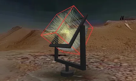
Your friend suggested to print a parabola to redirect the light towards the nonimaginum rod, but a lot of the light seems to miss the rod. Could you do better? The red cube is the one square meter print volume that your design must fit within.
Competition challenge
Design the highest efficiency concentrator to focus the light from the Anniversaria XX star onto your cylindrical nonimaginum rod.
Rules and Specifications:
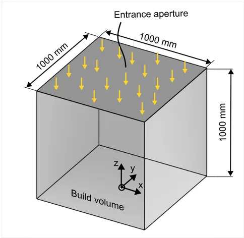
Build volume and entrance aperture specifications. The origin of the coordinate system is at the center of the bottom face (x=0, y=0, z=0). Valid coordinates are: x between -500mm and +500mm, y between -500mm and +500mm, and z between 0mm and 1000mm. However, you are able to adjust this during file upload if your design software uses another convention.
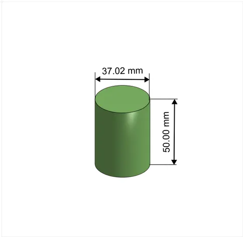
Nonimaginum rod dimensions. The reference point used for positioning the rod is the center point in the middle of the volume of the rod.
- Both the 3D printer and the solar tracker are limited to a maximum build volume of 1000 mm by 1000 mm by 1000 mm.
- The entrance aperture is considered to be the 1000 mm by 1000 mm square at the top of the build volume. No light enters the build volume through the side faces. Light is also blocked from leaving the build volume, so your entire optics and nonimaginum rod must fit within the build volume.
- The nonimaginum rod is a cylinder with a diameter of 37.02 mm and a length of 50.00 mm.
- The nonimaginum rod absorbs 100% of the light that hits any of its surfaces.
- You are free to choose the location and orientation of the nonimaginum rod, but it must be within the 1 m by 1 m by 1 m cube.
- Your 3D printer can print ideal faceted mirrors (specified by an STL file). It can also load STEP files, but please note that curved faces in the STEP files will be faceted before printing.
- Your 3D printer only supports files with a size up to 100 MB.
- The mirrors have a fixed reflectivity of 95%.
- The light has a uniform irradiance over the entrance aperture, and at each point the angular distribution is shaped like the letters “XX” in direction cosine space. The letters are constructed by two overlapping rectangles rotated 90 degrees with respect to each other. The radiant intensity is constant within the X pattern - there is no increase in intensity where the rectangles overlap. Dimensions are shown in the figures below.
- The goal is for the Nonimaginum Rod to help you get back to Earth in time for the conference, and attendees will be eligible for a special prize category. However, you are also welcome to participate even if you are unable to attend the conference in 2025.
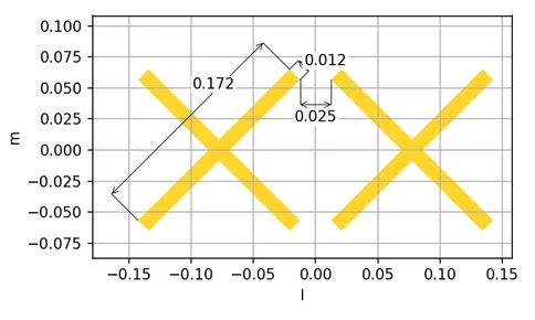
In direction cosine space, the angular distribution is shaped like the letters XX, constructed from overlapping rectangles with the dimensions shown. l is direction cosine in the x-direction, and m is direction cosine in the y-direction.
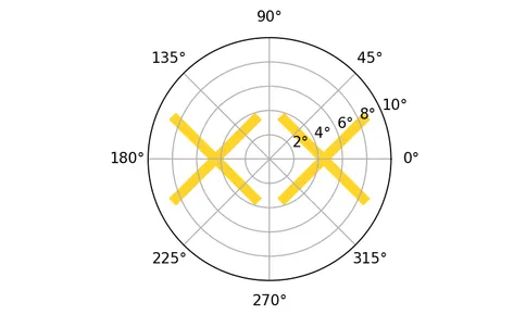
Angular distribution of the light displayed in polar coordinates.
Evaluation
The winning design will be the concentrator with the highest efficiency, as calculated in the submission portal. However, the committee may also choose to highlight other designs with interesting features or creative solutions. You can submit multiple designs to the competition if you want to explore different approaches.
Instructions
- Design your concentrator using any Optical Design or CAD software of your choice.
- Export your design as an STL file or a STEP file.
- Upload your file on the upload page, and receive an immediate evaluation of your concentrator’s efficiency.
- If you are satisfied with your design, submit it for the competition.
Submission Deadline: May 4, 2025 May 18, 2025 (Submissions are now closed. You can still test new designs in the upload portal, but the designs cannot be submitted.)
Getting Started
To help you get started, we’ve prepared some resources for popular optical design software packages. Click on your preferred software below to get started:
Synopsys LightTools - Conference Sponsor
To get started with LightTools, choose one of these options:
Option 1: Complete Project
Download a starting template containing:
- Ray source with the correct angular distribution
- Model of the nonimaginum rod
- Merit function to calculate efficiency
- A simple example reflector to get started
Option 2: Rayfile Only
Just the XX-shaped angular distribution to use in your own project
Lambda TracePro
Get started with TracePro using a rayfile for the XX-shaped angular distribution, and a model file for the Nonimaginum Rod:
Breault ASAP
Get started with ASAP using a rayfile for the XX-shaped angular distribution:
Download Rayfile (.dis)Ansys SPEOS
Get started with SPEOS using a rayfile for the XX-shaped angular distribution:
Download Rayfile (.ray)Ansys Zemax OpticStudio
Get started with Ansys Zemax OpticStudio using a rayfile for the XX-shaped angular distribution:
Download Rayfile (.sdf)No licence?
If you don’t have access to any of the above optical design packages, that’s no problem! Use nonimaging optics-based principles to design your concentrator, make it with any CAD tool, and test it directly in the submission portal.
Python & Build123D
Build123D is a Python library for building 3D models programmatically, built on the OpenCascade CAD kernel (the same kernel we use to import STEP files in our submission portal). We will demonstrate how you can use this to create a concentrator for the competition:
We start with importing numpy and the Build123D library:
import build123d as bd
import numpy as np
Next, we will make a parabola, with a focal length of 500 mm. We do this by making a grid of x,y points, and calculating the z value for each of these points. We then use OpenCascade’s surface fitting algorithm to create a surface from these points:
f_mm = 500  # Focal length 500 millimeters
p_x = np.linspace(-500, 500, 100)
p_y = np.linspace(-500, 500, 100)
p_X, p_Y = np.meshgrid(p_x, p_y)
p_Z = 1 / (4 * f_mm) * (p_X**2 + p_Y**2)
# Combine the x, y, and z points into a 3D array:
p_pts = np.dstack((p_X, p_Y, p_Z))
# Fit a surface to the points:
parabola = bd.topology.Face.make_surface_from_array_of_points(p_pts)
To illustrate making multiple faces, we will give the nonimaginum rod a small hemispherical “cap” over it. Note that we could also have used Build123D’s built-in primitives for this, but we want to demonstrate parametric curve fitting since you may want to use more complex mathematically defined shapes in your design. We create a grid of spherical coordinates, and then convert these to a set of x,y,z points that we again fit to a surface:
h_rad = 50  # Hemisphere radius: 50mm
# Define a grid of spherical coordinates:
h_theta = np.linspace(0, np.pi/2, 100)
h_phi = np.linspace(0, 2*np.pi, 100)
h_T, h_P = np.meshgrid(h_theta, h_phi)
h_X = h_rad * np.sin(h_T) * np.cos(h_P)
h_Y = h_rad * np.sin(h_T) * np.sin(h_P)
h_Z = h_rad * np.cos(h_T)
h_Z += 500  # Place it 500 millimeters above the parabola
h_pts = np.dstack((h_X, h_Y, h_Z))
hemisphere = bd.topology.Face.make_surface_from_array_of_points(h_pts)
Finally, all we need to do is to combine the two surfaces into a compound object, and export it to a STEP file:
concentrator = bd.topology.Compound([parabola, hemisphere])
bd.export_step(concentrator, 'concentrator.step', unit=bd.Unit.MM)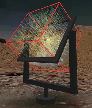
The parabola with a small spherical cap over the nonimaging rod. Currently the efficiency is not great, but maybe you can improve it?
You can find the complete example code here: concentrator_example.py.
If you don’t already have a Python environment that you want to use, we recommend using uv to run this code. Uv is a modern python package manager, and will take care of installing the correct version of python and the required dependencies for you. To run the script locally, you can follow these steps:
- Install uv from https://docs.astral.sh/uv/
- Download the script: concentrator_example.py
- Run the script:
uv run --python 3.12 concentrator_example.py
Other CAD tools
Don’t want to use Python? Here are some other CAD tools you can consider using to design your concentrator. All you need is something that can export your design to STEP or STL:
- Fusion 360 (free for students)
- Onshape (free for students)
- FreeCAD (open-source)
- OpenSCAD (open-source, somewhat limited but popular in the maker community)
Do you have questions?
Check out our FAQ page.
Are you ready?
Note: The submission deadline has passed and submissions are now closed. You can still test new designs in the upload portal, but the designs cannot be submitted.